Difference between revisions of "H6103"
From Hydrover
(→Description) |
|||
| Line 1: | Line 1: | ||
| − | + | __NOTOC__ | |
| − | = Description = | + | == Description == |
[[File:H6103.png|200px]] | [[File:H6103.png|200px]] | ||
| Line 6: | Line 6: | ||
like: lamps, solenoids, relays, ... | like: lamps, solenoids, relays, ... | ||
| − | = Software = | + | == Software == |
* Real Time O.S. | * Real Time O.S. | ||
* On-board advanced functions | * On-board advanced functions | ||
| − | == On-board advanced functions == | + | === On-board advanced functions === |
* Automatic input change detection | * Automatic input change detection | ||
| Line 20: | Line 20: | ||
* Analog accessory management | * Analog accessory management | ||
| − | = Hardware = | + | == Hardware == |
* Power 12V-24V (Max 36V) | * Power 12V-24V (Max 36V) | ||
| Line 30: | Line 30: | ||
* On-board CAN termination resistors | * On-board CAN termination resistors | ||
| − | = Pinout = | + | == Pinout == |
[[File:H6103-CONN.png|320px]] | [[File:H6103-CONN.png|320px]] | ||
Revision as of 00:43, 1 June 2017
Description
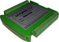
The H6103 ( aka IO Input Output ) is a slave board driven by H6105-D for sensing inputs and driving ON/OFF outputs like: lamps, solenoids, relays, ...
Software
- Real Time O.S.
- On-board advanced functions
On-board advanced functions
- Automatic input change detection
- Energy saving configurable for every single output
- Quadrature phase AB channel decoding
- Switch or proximity accessory management
- Encoder or optical rules accessory management
- Analog accessory management
Hardware
- Power 12V-24V (Max 36V)
- CPU ARM Cortex M3 100MHz
- Interfaces USB, CAN
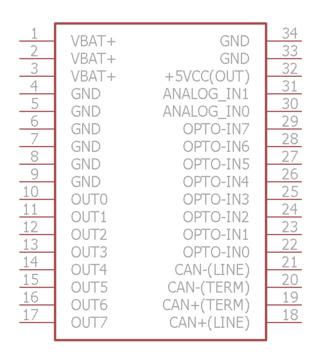
- Digital inputs 8 (opto-isolated 0-5V)
- Analog inputs 2 (0-5V)
- Digital Outputs 8 (Max 5A)
- On-board CAN termination resistors

